|
||||||||||
|
|
||||||||||
|
||||||||||
|
|
||||||||||

The report provides the following information for a 747-200 during high-altitude cruise.
| Reference Geometry | |
| Reference Area, Sref |
5,500 ft² 510.97 m² |
| Wingspan, b |
196 ft 59.74 m |
| Aspect Ratio, AR | 6.98 |
| Flight Conditions | |
| Altitude, h |
40,000 ft 12,192 m |
| Air Density, ρ |
0.00058735 slug/ft³ 0.30267 kg/m³ |
| True Airspeed, V |
871 ft/s 265.5 m/s |
| Angle of Attack, α | 2.4° |
| Mass Properties | |
| Weight, W |
637,000 lb 2,833,500 N |
| Total Aerodynamic Coefficients | |
| Coefficient of Lift, CL | 0.52 |
| Longitudinal Coefficients & Stability Derivatives | |
|
Coefficient of Lift at 0° Angle of Attack, CL0 | 0.29 |
|
Change in Lift Due to Angle of Attack, CLα | 5.5 |
Let us first apply the lift equation in the form presented above to solve for the lift under these conditions.

The answer turns out to be about 637,190 lb (2,834,400 N). We should have expected this result since the aircraft's weight listed in the above table is also very close to this value. Basic physics tells us that the lift and weight should be equal to each other for any aircraft in steady, level flight. If the two forces were not equal, the plane would not remain in level flight. Either the plane would climb to a higher altitude because the lift exceeded the weight and pulled it upward or the plane would descend due to the greater weight pulling it down.
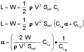
We can use this relationship to rearrange the lift equation and apply it in a new way. Since lift must equal weight for the plane to fly level, lift becomes a known value that we can use to solve for the lift coefficient. The lift equation then becomes:

We can again use the values provided above for the 747 to solve this equation.

Lo and behold, the lift coefficient is 0.52, exactly the value provided in the original data. This application of the lift equation may seem backwards, but engineers often use it during the preliminary design process of a new aircraft. A cruise speed as well as an approximate weight and size are typically specified when the design effort begins. These values can be used in the above equation to solve for the lift coefficient necessary to maintain cruise flight at those conditions. Once that coefficient in known, designers can determine what wing shape and airfoil section will best provide that lift coefficient while minimizing drag. Other factors obviously come into play since an aircraft does not spend its entire flight at steady and level conditions, but this technique is a common first step in the initial sizing and design of a new flying vehicle.
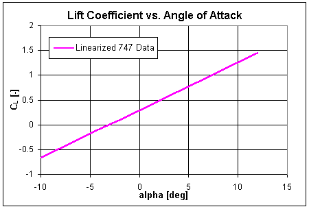
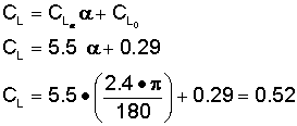
The NASA report described earlier also provides some additional data that we can use to further explore this subject. Recall a previous article that discussed a method of estimating the lift coefficient called Thin Airfoil Theory. This article introduced the following equation to approximate the behavior of the lift coefficient as a function of angle of attack in radians.
The variable CL0 represents the lift coefficient when angle of attack is zero while CLα is a stability derivative that defines the slope of the lift curve line. Values for both of these variables are provided in the above table. These parameters allow us to construct the linear portion of the 747 lift curve up to the angle of attack where wing stall would occur.

Since the NASA report also provides the angle of attack of the 747 in its cruise condition at the specified weight, we can use that information in the above equation to again solve for the lift coefficient. An example of this application can be seen in the following solved equation.

It should be no surprise that the resulting lift coefficient is 0.52 and agrees closely with the earlier calculations. We can also use the same technique to explore the opposite problem. If one knows the lift coefficient, CL0, and CLα, we can then rearrange the above relationships to solve for the angle of attack.

A solved example of this problem using the 747 data is shown below. Note that the angle of attack computed using this equation is in radians and must be converted before an answer in degrees is obtained.

The final solution turns out to be 0.04179 radians or 2.4°, exactly the value provided in the original data table. An alternative method to solve this problem is based on the equation discussed earlier that calculates the required lift coefficient given the aircraft weight. Once this coefficient were known, one could use the above graph of lift coefficient versus angle of attack to visually estimate the angle producing the desired coefficient.
This series of relationships illustrates many of the simple analysis techniques that engineers use in the design
and analysis of flying vehicles. Although our discussion was aided by 747 data derived from the NASA report, many
of these techniques can still be used without that wealth of information. The key to applying the equations
successfully is making reasonable assumptions to fill in whatever pieces may be unknown.
- answer by Jeff Scott, 27 November 2005
Related Topics:
Read More Articles:


|
Aircraft | Design | Ask Us | Shop | Search |

|
|
| About Us | Contact Us | Copyright © 1997- | |||
|
|
|||