|
||||||||||
|
|
||||||||||
|
||||||||||
|
|
||||||||||
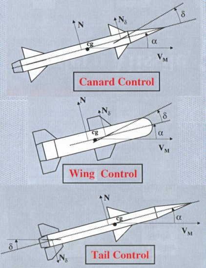
These control options can also be subdivided further. Tail control fins, for example, include three different types used to date. The first and most popular is the all-moving planar fin described above. Other missiles instead have fixed planar tail fins with movable flaps on the trailing edges. Examples of weapons employing this type of tail control fin include the Hellfire missile as well as the Brimstone based on the same basic design.
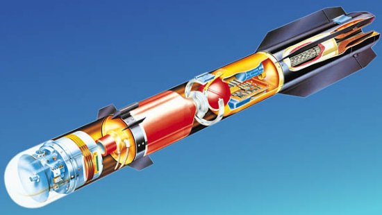
A third form of tail control is the grid fin. A grid fin looks much like a rectangular box filled with a lattice structure similar to a waffle iron or garden trellis. The grid is formed by small intersecting planar surfaces that create individual cells shaped like cubes or triangles. This box structure is inherently strong allowing the lattice walls to be very thin, reducing weight and the cost of materials. Unlike conventional fins aligned parallel to the direction of the airflow, a grid fin is arranged perpendicular to the flow allowing the oncoming air to pass through the lattice grid cells. An example of a generic grid fin concept is illustrated below.
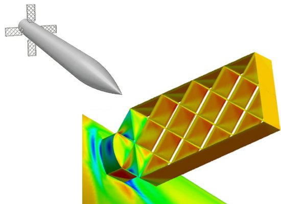
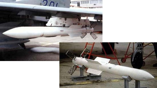
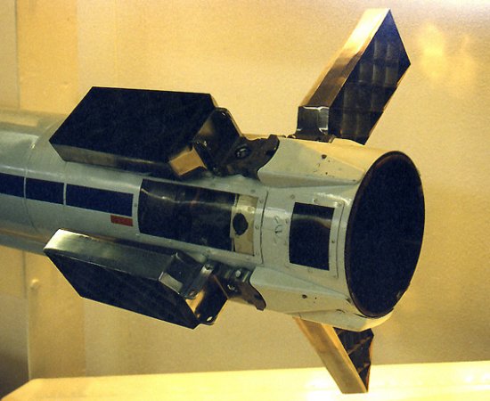
Grid fins have appeared on a number of Soviet missile designs since the 1970s, particularly ballistic missiles like the SS-12 'Scaleboard,' SS-20 'Saber,' SS-21 'Scarab,' SS-23 'Spider,' and SS-25 'Sickle.' These fins have also been used on Russian spacecraft including the N1 lunar rocket and the Soyuz TM-22 capsule. In the case of Soyuz, grid fins were used as emergency drag brakes. Perhaps the most recognized appearance of grid fins to date is on the Russian AA-12 'Adder' medium-range air-to-air missile.
All of these applications have been on vehicles traveling at high supersonic speeds. It is within this speed regime that grid fins are most attractive. The problem with planar fins is that they are relatively long surfaces. At high speeds, it becomes considerably harder to turn them because of the forces created by the mass of air rushing by. Imagine trying to open a door on a calm day versus trying to open it while a strong wind blows against it.
Missile fins are turned using servo mechanisms that rotate the fin to a new deflection angle. The sizes of these servos are dictated by the amount of torque it takes to rotate the fin about its axis. The large size of conventional planar fins causes their center of pressure to move over a relatively large region. This motion results in large hinge moments, which is a measure of how much torque it takes to rotate the fin to a new position.
The primary advantage of grid fins is that they are much shorter than conventional planar fins in the direction of the flow. As a result, they generate much smaller hinge moments and require considerably smaller servos to deflect them in a high-speed flow. The small chord length of grid fins also makes them less likely to stall at high angles of attack. This resistance to stall increases the control effectiveness of grid fins compared to conventional planar fins.
Another important aerodynamic characteristic of grid fins concerns drag, although it can be an advantage or a disadvantage depending on the speed of the airflow. In general, the thin shape of the lattice walls creates very little disturbance in the flow of air passing through, so drag is often no higher than a conventional fin. At low subsonic speeds, for example, grid fins perform comparably to a planar fin. Both the drag and control effectiveness of the lattice fin are about the same as a conventional fin in this speed regime.
The same behavior does not hold true at high subsonic numbers near Mach 1. Drag rises considerably higher and the fins become much less effective in this transonic region because of the formation of shock waves. Even though the weapon may be flying below Mach 1, the airflow through the cells of the fin can be accelerated to supersonic speeds creating normal shock waves within the grid. This behavior is often referred to as a choked flow that blocks incoming air from passing through and increases drag. The drag grows even worse for a weapon flying slightly faster than Mach 1 since a detached normal shock wave, also called a bow shock, can form in front of the fin. This bow shock worsens the effect of the choked flow by forcing additional air to spill around the fin further increasing drag and reducing control effectiveness.
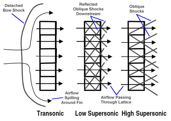
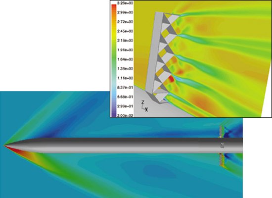
This situation improves as the weapon accelerates beyond the transonic region, approximately Mach 0.8 to 1.3. At higher speeds, the normal shock is "swallowed" and shock waves are instead formed off the leading edges of the lattice at an oblique angle. The oblique angle is still fairly large at low Mach numbers, causing the shock waves to reflect off the downstream lattice structure. These reflections can create a large number of shock waves within the grid fin resulting in high drag. As Mach number increases, however, the smaller the oblique shock angle becomes until the shock passes through the structure without intersecting it. This behavior causes drag to drop while control effectiveness increases considerably compared to a planar fin.
Because of their shape and small chord length, a further advantage of grid fins is they can easily be folded against the missile body and deployed relatively easily. This folding makes the weapon more compact and easier to store or transport. This advantage is particularly attractive for weapons designed for internal weapons bays on stealth aircraft like the F-22 and F-35. Compact packaging is also important for submunitions dispersed by high-speed cruise missiles. Grid fins have been proposed as a means of controlling weapons ejected from supersonic munition dispensers with the dual use of providing speed brakes to decelerate the submunitions to subsonic speeds.
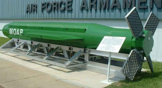
This packing efficiency helps explain why grid fins have been implemented on the enormous Massive Ordnance Air Blast (MOAB) bomb developed by the United States. This gigantic weapon, weighing over 20,000 lb (9,070 kg), is carried into combat aboard the C-130 Hercules. The bomb is fitted with four large grid fins that fold against the bomb body. The weapon is launched by being pushed out of the C-130's cargo bay aboard a sled equipped with a stabilizing parachute. Once free of its sled, the four grid fins are deployed to steer the weapon as it maneuvers to a pre-programmed target using GPS signals for guidance. Grid fins have also been proposed for smaller bombs like JDAM and Small Diameter Bomb, particularly when released from internal weapon bays. Given the slow speeds these weapons fly at, the primary advantage of lattice fins appears to be packaging rather than lower drag or increased control effectiveness.
Nevertheless, an important disadvantage of grid fins that may limit their applications to future weapons is radar cross section. The cube-shaped cells formed by the lattice structure tend to create very strong radar reflections that would be very undesirable in a weapon designed for low observability. This limitation might be minimal for short-range weapons like bombs but could be a significant concern for applications like long-range cruise missiles.
Despite these drawbacks, the improved maneuverability grid fins offer at high supersonic speeds and high angles of
attack have resulted in several grid fin research efforts in recent years. Western nations like the US and Germany
performed a great deal of experimental work on lattice fin concepts during the 1980s. More recent efforts have
focused on using computational fluid dynamics (CFD) to better understand the characteristics of the flow passing
through the fins in order to better optimize their performance. Thanks to this research and the advantages of the
lattice design, grid fins could likely become a more common feature on guided weapons of the future.
- answer by Jeff Scott, 12 February 2006
Read More Articles:


|
Aircraft | Design | Ask Us | Shop | Search |

|
|
| About Us | Contact Us | Copyright © 1997- | |||
|
|
|||