|
||||||||||
|
|
||||||||||
|
||||||||||
|
|
||||||||||
| Aircraft | Takeoff Weight | Takeoff Speed |
|---|---|---|
| Boeing 737 |
100,000 lb 45,360 kg |
150 mph 250 km/h 130 kts |
| Boeing 757 |
240,000 lb 108,860 kg |
160 mph 260 km/h 140 kts |
| Airbus A320 |
155,000 lb 70,305 kg |
170 mph 275 km/h 150 kts |
| Airbus A340 |
571,000 lb 259,000 kg |
180 mph 290 km/h 155 kts |
| Boeing 747 |
800,000 lb 362,870 kg |
180 mph 290 km/h 155 kts |
| Concorde |
400,000 lb 181,435 kg |
225 mph 360 km/h 195 kts |
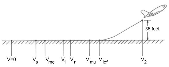
But you might be wondering just how these speeds are determined. Commercial airliners are certified under the Federal Aviation Administration (FAA) Federal Aviation Regulation (FAR) Part 25 which specifies takeoff velocity requirements that must be observed by transport aircraft. The progression of takeoff speeds dictated by these regulations is illustrated in the following figure.

This diagram starts with the plane at rest, indicated by V=0. The first critical speed encountered during the takeoff run is the stall speed, Vs. The stall speed is an important quantity throughout aerodynamics as it dictates the slowest speed at which an aircraft can travel and generate just enough lift to remain or become airborne. This velocity is heavily dependent upon the configuration of the plane, primarily the state of flaps, slats and other lift-control devices. Determining the stall speed is relatively straightforward using our handy dandy friend, the lift equation:

In this case, we know that we need enough lift (L) to counteract the takeoff weight (W), we know the
reference area, and we know the
density at the takeoff altitude. The lift coefficient that concerns us
here is the maximum lift coefficient in the takeoff configuration (typically flaps down at 5° or 10°) represented
by

Even though the plane is capable of taking off as soon as the stall speed is reached, it is a very unstable condition. Even the slightest change in the orientation of the plane or the condition of its control surfaces will cause the wing to lose lift (i.e. the wing stalls, hence the name "stall" speed) and the aircraft will drop back onto the runway.
Due to the danger of trying to takeoff at stall speed, a number of additional speed requirements have been implemented for safety reasons. The first of these relates to multi-engined aircraft, which covers all commercial airliners. Should an engine fail during the takeoff run, there is usually a yawing moment since the engine(s) on one side of the plane produce more thrust than those on the other side. A yawing moment, which causes the nose to turn side-to-side, is countered by a deflection of the rudder, which produces a yaw moment in the opposite direction. The two moments will then cancel each other out and keep the plane headed straight down the runway. Below a certain speed, there simply is not enough aerodynamic force generated by the rudder to produce the correcting yaw. This velocity is called the minimum control speed, Vmc.
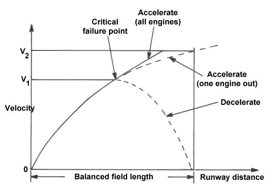
The next critical speed, which must be at least as fast as Vmc, is also related to the failure of an engine during the takeoff run. If the engine fails fairly far down the runway, the plane might have enough speed to continue the takeoff safely. Conversely, if the engine fails early in the takeoff, there ought to be enough runway left to abort the takeoff and come to a stop. But what if the engine fails somewhere in between? To provide the pilot with some definite criteria on which to make a decision, the FAR Part 25 specifies a critical engine-failure speed, V1. Below this speed, the pilot should abort and bring the plane to a stop if an engine fails. If the engine fails after the aircraft has exceeded V1, he should continue the takeoff using the remaining engines. The critical engine speed therefore defines the point on the runway at which the distance needed to stop is exactly the same as the that required to reach takeoff speed. The resulting total takeoff distance is correspondingly known as the balanced field length.

The next velocity of interest to us is that at which the aircraft can begin to rotate its nose into the air, conveniently called the rotation speed, Vr. While Vr must be at least 5% greater than Vmc, it need not be any greater than V1.
Next comes the minimum unstick speed, Vmu, which defines the point at which the aircraft could take off if the maximum possible rotation angle were reached. This maximum angle would occur if the tail of the plane were to actually scrape the ground.
Since such a takeoff would be damaging to the plane and most unnerving to passengers, the aircraft actually lifts off at a slightly greater velocity called the liftoff speed, Vlof. Liftoff speed must be at least 10% greater than Vmu when all engines are operating and 5% greater when one engine has failed.
Now that our happy little plane has finally become airborne, it accelerates into takeoff climb speed, V2, which must be reached at an altitude high enough to clear a given obstacle. For FAR 25 aircraft, the obstacle clearance height is 35 ft (10.7 m). The takeoff climb speed must be at least 20% greater than stall speed, Vs, and 10% greater than Vmc.
These speeds are summarized below.
| Speed | Description |
FAR 25 Requirement |
|---|---|---|
| Vs | stall speed in takeoff configuration | - |
| Vmc | minimum control speed with one engine inoperative (OEI) | - |
| V1 | OEI decision speed | = or > Vmc |
| Vr | rotation speed | 5% > Vmc |
| Vmu | minimum unstick speed for safe flight | = or > Vs |
| Vlof | liftoff speed |
10% > Vmu 5% > Vmu (OEI) |
| V2 | takeoff climb speed at 35 ft |
20% > Vs 10% > Vmc |
Read More Articles:


|
Aircraft | Design | Ask Us | Shop | Search |

|
|
| About Us | Contact Us | Copyright © 1997- | |||
|
|
|||