|
||||||||||
|
|
||||||||||
|
||||||||||
|
|
||||||||||
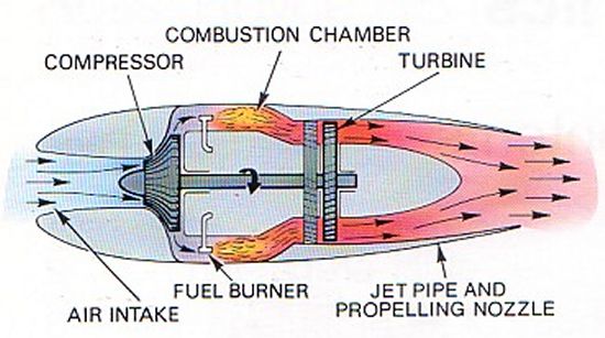
In order to better understand the parts of a jet engine and how this form of propulsion works, let us briefly revisit the different types of jet engines. The earliest form of jet propulsion was the turbojet. This type of powerplant employs a series of compressor blades mounted on rotating disks that squeeze incoming air to a higher pressure and temperature. The compressed air is then mixed with fuel and ignited. The high temperature air passes through another series of rotating blades called a turbine, which causes this turbine to spin. The turbine rotors are attached to a central shaft running the length of the engine, so the turbine's spinning motion causes this shaft to rotate as well. Also attached to the same central shaft is the compressor section at the front of the engine. This connection between the turbine and compressor sections causes the compressor stages to continue spinning, bringing in additional air to keep the engine functioning in a repeating cycle. Once the airflow moves past the turbines, it is exhausted through a nozzle. The expansion of the high pressure gases against the nozzle walls creates thrust that pushes the engine forward, as well as the vehicle it is attached to.
Another type of jet that is similar to but more efficient than the turbojet is the turbofan. A turbofan uses the same components described above with the addition of a large fan in front of the compressor section. This fan is connected to the same central shaft that turns the compressor blades so that the fan also rotates. As it does so, the fan accelerates a wide column of air to further increase thrust. Air passing through the center portion of the fan enters the compressor where it moves through the core of the engine just like on a typical turbojet. Air accelerated through the fan's outer diameter, however, flows around the engine core without passing through it. This process can be better understood by studying an animation of airflow through a turbofan.
There are two basic types of turbofans that are differentiated by the relative amount of air that flows through the fan and around the engine core versus the amount of air that flows through the core itself. A turbofan with a low-bypass ratio means that most of the air flowing through the engine passes through the turbojet core and very little through the outer fan bypass duct. Such engines are most common on military combat aircraft like fighters. Today's commercial airlines, like the 757, are instead fitted with high-bypass turbofan engines. A high-bypass turbofan consists of a very large diameter fan and a much smaller-diameter turbojet core within.
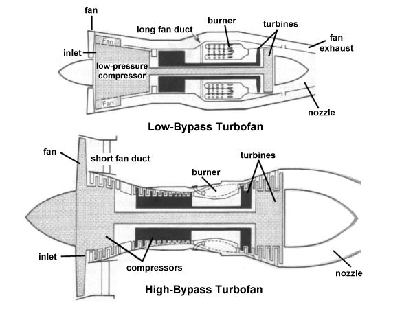
As shown in the above diagram, a turbofan contains many rotating compressor and turbine disks, all of which are smaller than the fan at the front of the engine. The rotary components within a high-bypass turbofan, in particular, are often only a small fraction of the fan diameter. Most specifications describing the overall size of an engine will list the fan diameter since this measurement defines the engine's maximum width. Our earlier article about the 757 uses this dimension to compare the diameter of the engine nacelle to that of the fuselage.
With that introduction aside, let's take a closer look at the specific question of debris found at the Pentagon following the attack on 11 September 2001. While researching this topic, we came across many websites claiming that it was not American Airlines Flight 77 that was hijacked and purposefully crashed into the Pentagon during the terrorist attack that morning. The authors of these sites instead believe that any of a variety of military aircraft, cruise missiles, or other weapons were used by the US government to attack the Pentagon, and the stories of terrorist hijackings were simply a cover up for the sinister scheme.

According to the accepted story, American Airlines Flight 77 was hijacked by five al Qaeda terrorists as it was traveling from Washington DC to Los Angeles. The aircraft involved in this hijacking was a Boeing Model 757-200 with the Boeing customer code 757-223 and the registration number N644AA. This same aircraft is pictured above in a photo taken at Logan International Airport in Boston on 7 August 2001. The terrorists steered the plane into the west side of the Pentagon killing 59 passengers and crew as well as 125 victims on the ground.
Those who doubt this version of events point to wreckage at the Pentagon as proof that some other kind of aircraft or missile was actually responsible for the attack. Probably the one piece of debris that has prompted the most debate is the following photo of what looks like a rotary disk from the interior of the plane's engine. This disk could be part of a fan, a compressor, or a turbine rotor from inside the engine, but the blades are not present and were presumably knocked off in the impact.

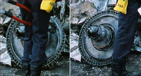
Based on the sizes of the person standing next to the debris and other objects in the photographs that we can use for comparison, it has been estimated that the disk is approximately 25 to 30 inches (63.5 to 76.2 cm) across. Obviously, this piece is far smaller than the maximum engine diameter of 6 feet (1.8 m) or more leading many to draw the conclusion that the item is not from a 757 engine. That conjecture causes conspiracy theorists to believe that a much smaller vehicle must have struck the Pentagon instead.
However, we have already seen that rotating components within a turbofan engine can vary widely in size. In order to determine whether this component could have possibly come from a 757, we need to take a closer look at the engine installed aboard the aircraft registered N644AA. Boeing offered two different engine options to customers of the 757-200. Airlines could choose between the Pratt & Whitney PW2000 family or the Rolls-Royce RB211 series. The particular engine model chosen by American Airlines for its 757 fleet was the RB211-535E4B triple-shaft turbofan manufactured in the United Kingdom. A drawing illustrating the overall size of this engine is pictured below.
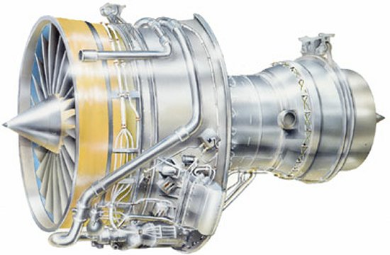
Note the relative sizes of the forward portion of this engine compared to the central core. Clearly, the section housing the fan is much wider than the turbojet core that contains the compressor and turbine components. We can get a clearer view of the relative sizes of components within this engine in the following cut-away drawing of the RB211-535.
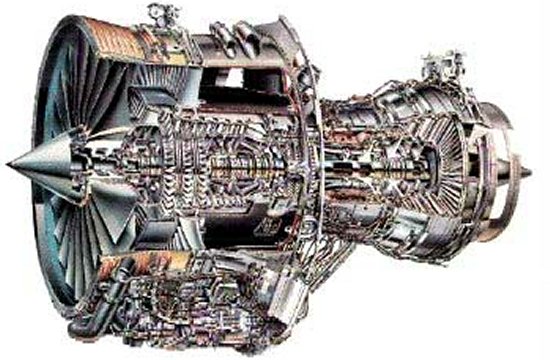
Using these images and other diagrams of the RB211-535 engine, we can obtain approximate dimensions of the engine's rotary disks for comparison to the item found in the Pentagon rubble. Our best estimate is that the engine's twelve compressor disk hubs (without blades attached) are about 36% the width of the fan. The five turbine disk hubs appear to be slightly smaller at approximately 34% the fan diameter. According to Brassey's World Aircraft & Systems Directory and Jane's, the fan diameter of the RB211-535E4B engine is 74.5 inches (189.2 cm). It then follows that the compressor disk hubs are approximately 27 inches (69 cm) across while the turbine disk hubs are about 25 inches (63.5 cm) in diameter. Both of these dimensions fit within the range of values estimated for the engine component pictured in the wreckage at the Pentagon.
We can take this analysis a step further by also exploring some of the alternate theories that have been put forward by those believing this object comes from a different aircraft. Two of the most common claims we have seen suggest that the plane used in the attack was a Douglas A-3 Skywarrior or a Northrop Grumman RQ-4 Global Hawk. The A-3 is an airborne jamming aircraft originally ordered by the US Navy during the 1950s. The type is now retired from front-line service though a handful are still used for testing purposes by the defense contractor Raytheon. The Global Hawk is an unmanned aerial vehicle used by the Air Force for reconnaissance missions. Neither of these planes bears more than a superficial resemblance to the 757, but we will accept the possibility that they could be mistaken for a commercial airliner given the confusion on September 11.
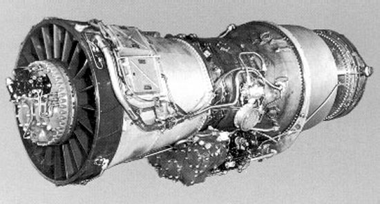
For the sake of this investigation, the only issue we shall consider is the engines that power both planes. The A-3 was equipped with two Pratt & Whitney J57 turbojets like that pictured below. The J57 dates to the early 1950s and is rather antiquated by today's standards.
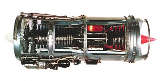
For some reason, most of the conspiratorial sites instead make extensive reference to the A-3 being powered by a Pratt & Whitney JT8D engine. Moreover, these sites claim that the JT8D is a turbojet. The JT8D is actually a low-bypass turbofan that was developed for use aboard commercial aircraft like the 727 and 737. We have not found any source that indicates the JT8D was ever used on the A-3 Skywarrior, so it is unclear why the originators of the A-3 theory are so infatuated with this particular powerplant. Nevertheless, we will include it in our investigation for completeness.
The Global Hawk, meanwhile, is powered by a single Rolls-Royce AE3007H turbofan. The AE3007 is built by the Allison Engine division of Rolls-Royce located in Indianapolis, Indiana.
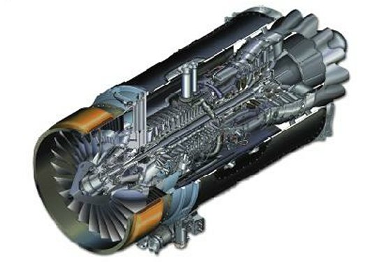
Using photos and cut-away drawings of these three engines, we can estimate the diameters of the compressor and turbine rotor hubs just as we did for the RB211. While the compressor and turbine disks on the J57 and JT8D are larger by percentage than those of the RB211, the maximum diameters of all three engines are considerably smaller as summarized in the following table.
| Engine | Overall Diameter | Compressor Hub Diameter (estimated) |
Turbine Hub Diameter (estimated) |
|---|---|---|---|
| PW J57 | 40.5 in (102.9 cm) | 16 in (40.6 cm) | 18 in (45.7 cm) |
| PW JT8D | 49.2 in (125 cm) | 21.5 in (54.6 cm) | 22.5 in (57.1 cm) |
| RR AE3007H | 43.5 in (110.5 cm) | 14 in (35.6 cm) | 15 in (38.1 cm) |
This analysis indicates that all three of these engines are too small to match the engine component photographed at the Pentagon. Some sites also suggest the part might be from the aircraft's auxiliary power unit (APU). An APU is essentially a small jet engine mounted in the tail of an aircraft that provides additional power, particularly during an emergency. However, APUs tend to be much smaller than jet engines, and the component pictured at the Pentagon is too large to match any found in an APU. It has also been suggested that the attack was conducted by a cruise missile like the Tomahawk or Storm Shadow, but these and other weapons are powered by engines no more than 15 inches (38 cm) across. These powerplants are obviously far too small to account for the Pentagon wreckage.
Whatever piece this is, it appears to be only the central hub of a compressor or turbine stage. Normally, each of these rotating stages would be fitted with several curved blades mounted along its circumference. These blades were apparently knocked off the rotor hub found in the wreckage due to the force of the impact. The loss of these blades is unfortunate since different manufacturers often adopt unique shapes for their fan, compressor, and turbine blades that would make the source of the component much easier to identify. Nonetheless, we have been able to locate the following picture of the intermediate pressure compressor section of the RB211 that appears to match several characteristics of the Pentagon debris. Note that this photo appears to be from the RB211-524 which is an uprated relative of the RB211-535 used on the Boeing 747 and 767. This engine model contains seven intermediate pressure compressor stages compared to the six of the RB211-535. However, the compressor disks used on both engines are believed to be nearly identical.
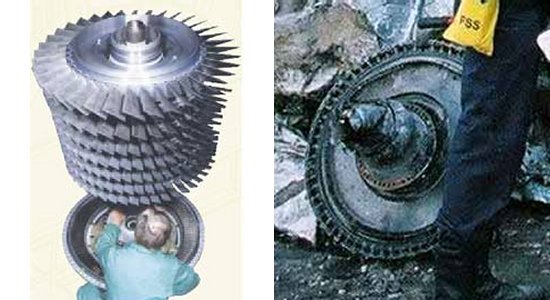
One similarity between the two photos can be seen in the cleats along the edge of the Pentagon object. These devices are called dovetail slots and provide attachment points for the compressor blades. The shapes of these slots on the Pentagon wreckage appear to match those on the RB211 assembly shown on the left. Furthermore, the "nosepiece" jutting out from the center of the disk in the Pentagon photo shares commonalities with the central shaft visible in the RB211 photo.
The above analysis indicates that the Pentagon debris does in fact match the characteristics of a rotor disk from the Rolls-Royce RB211-535. The wreckage is most likely a compressor stage given the shape of the dovetail slots. It is difficult to be certain exactly which compressor disk it is since the six rotors of the intermediate pressure section and six high pressure compressor disks are of similar size. The primary difference from one compressor to the next is the smaller span of the compressor blades as the air flows further into the engine, but these blades are no longer attached to the wreckage. However, additional clues in the photo suggest the rotor disk is probably from the high pressure section or perhaps the very last disk of the intermediate pressure compressors.
We believe the disk is most likely a high pressure compressor because of the shape of the piece jutting from its center. This item is part of the central shaft that runs the length of the engine to connect the rotating stages of the fan, compressor, and turbine. The RB211 is described as a triple-shaft or triple-spool turbofan since it uses three concentric shafts to drive the various rotating elements of the engine. These shafts are differentiated by the relative pressure of the gases passing through the rotor stages attached to them. The longest shaft with the smallest diameter located closest to the centerline connects the low pressure (LP) engine components. This shaft is rotated by the LP turbines, located just ahead of the nozzle, and drives the large fan at the front of the engine.
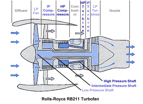
The LP shaft rotates within a shorter, larger diameter shaft that drives the intermediate pressure (IP) system. This shaft rotates at a higher rate and connects the IP turbine stage to the six IP compressor disks. The third concentric shaft is the shortest with the largest diameter and highest rate of rotation to drive the engine's high pressure (HP) system. This shaft connects the HP turbine to the six HP compressors. The debris photographed at the Pentagon appears to be connected to three concentric shafts of increasing diameter, suggesting that it most likely comes from the high pressure system of a triple-spool turbofan like the RB211-535.
Alternatively, this disk could be the last of the intermediate pressure compressor rotors and the larger diameter shaft we see might be the start of the shaft on which the high pressure compressors are mounted. If a photo of the opposite side of the disk were available, it should be easier to tell exactly which section of compressors it comes from. Nevertheless, the evidence documented above clearly shows that the size and shape of this debris is consistent with the RB211 turbofan carried by a 757 but not so with engines used aboard smaller aircraft and missiles.
Since this article was first published, we have received several comments from readers citing a quote from Rolls-Royce spokesman John W. Brown who said, "It is not a part from any Rolls-Royce engine that I'm familiar with..." The critics go on to suggest that this statement disproves all of our analysis indicating the disk is a compressor stage from the Rolls-Royce RB211-535. However, a simple review of the source of this quote shows just the opposite. The material is from an article titled "Controversy Swirling Over September 11 Pentagon Mystery: Industry Experts Can't Explain Photo Evidence" written by Christopher Bollyn that appeared on the pro-conspiracy website American Free Press.
The article describes John Brown as a spokesman for Rolls-Royce in Indianapolis, Indiana. This location is home to the Allison Engine factory that builds the AE3007H turbofan used aboard the Global Hawk. Brown's quote regarding the mystery wreckage states that, "It is not a part from any Rolls Royce engine that I'm familiar with, and certainly not the AE 3007H made here in Indy." Furthermore, the article correctly notes that the RB211 is not built in Indianapolis but at the Rolls-Royce plant in Derby, England. Since Brown is a spokesman for Allison Engines, which was an independent company that only became a subsidary of Rolls-Royce in 1995, it stands to reason that an engine built in the United Kingdom would be one he's not "familiar with." The article even goes on to point out that Brown could not identify specific parts from one engine or another since he is not an engineer or assembly line technician who would be familiar with the internal components of turbine engines.
For what it's worth (and it isn't worth much, given the author's apparent lack of journalistic skill), the Bollyn article actually supports the evidence assembled on this site. The article provides quotes from Honeywell Aerospace indicating that the piece did not come from an APU, from Allison Engines suggesting that it is not a component found in the turbofan used on Global Hawk, and from Teledyne Continental Motors indicating that it is not part of a cruise missile engine. All of these conclusions match those explained above.
Perhaps an even more conclusive piece of wreckage was found among other debris photographed at the Pentagon following the impact. The component shown below has appeared on several conspiracy theory websites claiming that it does not match any known component of the RB211 and must come from a different type of engine.
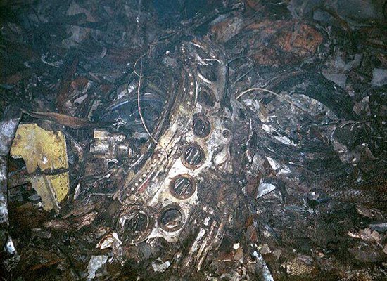
This item appears to be part of the casing of the combustion section. This portion of a jet engine is located aft of the compressors, and it is here that the high pressure air is mixed with fuel and ignited. The circumference of this circular casing contains several holes through which fuel injectors spray the jet fuel needed for combustion. The number, size, and shape of these nozzle holes is generally unique to a particular engine type and can be used to identify the engine model it comes from. Based on the curvature of the debris, the piece shown here appears to be about half of the total combustor case. We can count six nozzle ports along its circumference from the region nearest the floor around to the top, which represents about one-third of the total case. We can also see six screw holes along the circumference of each nozzle port that are used to attach the fuel injectors.
The best photos we have found illustrating the design of this part on the RB211-535 series engine come from the Boeing 757 maintenance manual. A diagram from this manual shown below illustrates components of the RB211-535 high pressure system and its location relative to the rest of the engine.
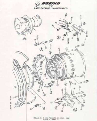
An even better close-up view of the combustion case is provided below. Note the overall design pattern of the fuel injector ports including the shape of the holes, the spacing between them, and their relative sizes compared to the diameter of the case itself. Also note the locations of the six screw holes around the circumference of each nozzle port. There also appear to be a total of 18 injector holes around the circumference of this casing, and six of these holes can be found over one-third of the case diameter. All of these measurements match up perfectly to the Pentagon photo.
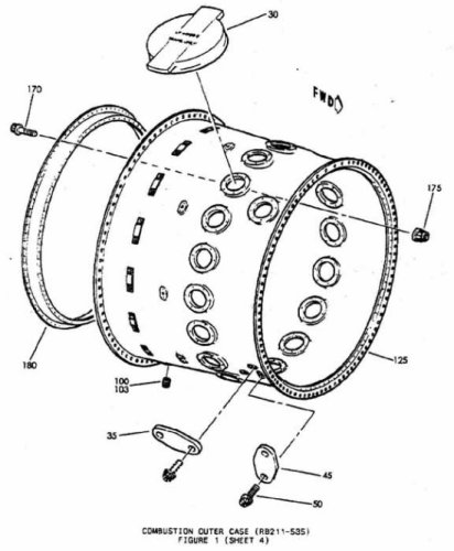
In summary, we have studied two key pieces of wreckage photographed at the Pentagon shortly after September 11 and found them to be entirely consistent with the Rolls-Royce RB211-535 turbofan engine found on a Boeing 757 operated by American Airlines. The circular engine disk debris is just the right size and shape to match the compressor stages of the RB211, and it also shows evidence of being attached to a triple-shaft turbofan like the RB211. While many have claimed the wreckage instead comes from a JT8D or AE3007H turbofan, we have shown that these engines are too small to match the debris. Furthermore, we have studied what clearly looks like the outer shell of a combustion case and found that its fuel injector nozzle ports match up exactly to those illustrated in Boeing documentation for the RB211-535 engine. There is simply no evidence to suggest these items came from any other engine model than the RB211-535, and the vast majority of these engines are only used on one type of plane--the Boeing 757.
Nonetheless, the various sites we have discovered over the course of answering this question raise a number of
other questions about pieces of wreckage found at the crash site. While this article focused only on the engine
debris asked about in the original question, we may revisit this subject in the future to better explore the claims
of a Pentagon cover up following September 11.
- answer by Joe Yoon
- answer by Jeff Scott, 12 March 2006
Update!
One common question we've seen on sites critical of a Boeing 757 striking the Pentagon is why is there so little engine wreckage. The only identifiable engine components seen so far are the two discussed above. Since these pieces represent so little of the two large engines carried by a 757, those believing in conspiracy suggest that these small items were planted and the lack of more substantial debris is proof of a cover-up. If a 757 truly hit the Pentagon, they argue, then where is the rest of the two engines? This argument ignores the simple fact that a lack of photos of other engine parts does not mean that none existed, only that other engine components were either not photographed or the photos have not yet been released.
Luckily, several readers have pointed out an additional picture that was released as an exhibit during the Zacarias Moussaoui terrorist trial in 2006. This photo, shown below, clearly includes a sizeable and relatively intact portion of a gas turbine engine.
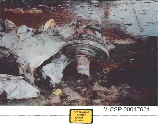
This debris appears to contain two rotating engine disks with part of the engine's central shaft protruding forward. Behind the two disks is another component called a frame. Frames are fixed, non-rotating components that provide attachment points holding the engine together. This debris must come from the aft section of an engine given the shape of the blade attachment points visble along the circumference of the two rotating disks. These attachments have a highly cambered, or curved, banana-like shape indicative of the blades used in the turbine section of a jet engine. The blades used on fan and compressor stages, by comparison, have a much straighter and less curved shape.
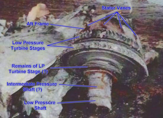
The RB211-535 engine used on the 757 contains five turbine disks--three low pressure turbines that power the fan, one intermediate pressure turbine driving the intermediate pressure compressors, and one high pressure turbine that turns the high pressure compressors. The debris shown here contains two of the three low pressure turbines and possibly the remains of the third. The protruding shaft also appears to be composed of two separate shafts of differing diameter. A small portion of the inner shaft, from the engine's low pressure system, appears to protrude from inside a second larger diameter shaft surrounding it. This larger diameter shaft corresponds to the intermediate pressure system and would connect to an additional turbine disk that is no longer attached.
Though it is difficult to conclusively identify these components as part of an RB211-535 engine without better pictures of an intact engine for comparison, perhaps the most identifiable object shown in debris is the aft frame. Along the circumference of this frame are several fixed blades called stators that help guide the air as it flows through the engine. We can see the remains of four of these stators in the photo over about a third of its diameter.
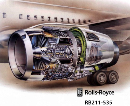
The above illustration from Rolls-Royce shows another cut-away of the RB211-535 that provides a good view of the internal components of the engine. In particular, note the frame just aft of the turbine stages. The spacing of the stator vanes shown here matches those seen in the Pentagon photo well and provides additional evidence that the debris is in fact from an RB211 engine.
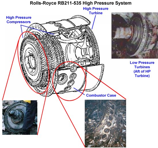
To give a better idea of how the three engine components we have discussed relate to one another, the above image
shows a diagram of the high pressure system within the RB211-535 engine. Also included are the objects identified
in the Pentagon wreckage and their relative locations within the engine. As discussed in the main article, all
three of these pieces of debris are identical matches to or at least consistent with the components found in the
Rolls-Royce RB211-535 turbofan aboard a Boeing 757.
- answer by Jeff Scott, 6 May 2006
Related Topics:
Read More Articles:


|
Aircraft | Design | Ask Us | Shop | Search |

|
|
| About Us | Contact Us | Copyright © 1997- | |||
|
|
|||